Metallic Ink Pigment Guide
Metallic ink pigment application on printed goods is becoming increasingly important as their use becomes more prevalent in the packaging and label industry in an effort to improve brand identification and brand recognition for products in the supermarket. The human eye has always been attracted by shiny silver and golden effects, which is why these colors are so appealing. Today, there are many technologies on the market that can be used to achieve metallic effects on film, paper and carton-based packaging. These technologies come with certain benefits and drawbacks.
This paper focuses on metallic ink pigments incorporated in inks.
Metallic ink pigment is used in all market segments of the packaging and printing industry and involve different binder chemistries and curing mechanisms for all printing applications. While all solutions are available on the market in theory, it can be a challenge to find the best match when chemistry and market segment regulations (e.g. tobacco and food packaging), governmental regulations (e.g. VOC regulations, dangerous goods regulations, low migration) and brand owner regulations (e.g. NESTLÉ) are taken into account.
Metallic Ink Pigment Guide
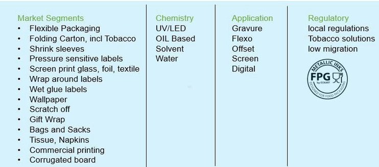
Figure 1: Table of market segments in which metallic inks are used in different chemistries, applications and regulatory classifications.
To understand the characteristics and usage of these pigments, this paper covers most of the important facts concerning handling.
Effect Pigment Production
Basics of aluminum effect pigment production
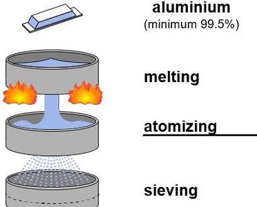
The starting point for the production of metallic ink pigment is pure metal ingot. The quality of the aluminum can greatly impact subsequent steps. Aluminum is available in different grades of purity. Common impurities include iron and copper, which can affect stability in waterborne and UV inks, but heavy metals like lead and arsenic are also common, which can limit use in food packaging, for example.
Figure 2 describes the first step of aluminum metallic ink pigment production: from the aluminum ingot to the raw material of metallic ink pigments: fine, ‘atomized’ aluminum powder. In this process step aluminum is melted in an oven and sprayed with compressed air to obtain a fine aluminum powder.
Figure 2: Creation of fine metal powder from an aluminum ingot.
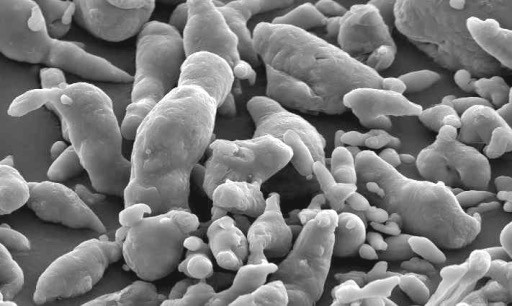
Depending on the parameters of the melted aluminum spraying process, the obtained powder can be irregular or round-shaped, which influences the characteristics of the metallic ink pigment after milling.
Figure 3: Microscopic image of an irregular powder after melting and spraying aluminum.
Figure 3 shows a microscopic image of an aluminum powder obtained by the irregular powder spraying process. The image shows fine and coarse powder components, which make up the particle size distribution after milling and are responsible for brilliance and hiding power in an ink layer.
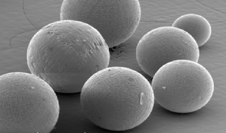
By comparison, Figure 4 shows an aluminum powder that was produced using a different method to obtain optimal round-shaped particles.
Fifure 4: Regular aluminum powder obtained after melting and spraying aluminum.
Once the aluminum powder is created, it is used as a raw material in a milling step to roll the particles out like pizza dough and obtain microscopic metallic mirrors. A solvent (e.g. mineral spirit) and a lubricant are used to deform the aluminum powder in a wet milling process. The role of the lubricant is to keep the pigments separated during milling.
As mentioned before, the shape of the used raw material (aluminum powder) significantly determines the final product – this can be seen in Figure 5. The microscopic image shows that irregular aluminum powder results in an irregular cornflake type of metallic ink pigment after milling, while spherical aluminum powder becomes a regular coin shaped (‘silver dollar’) metallic ink pigment after milling. As can be seen in the cornflake image (Figure 5, upper right corner), the pigments are not as thick as the silver dollar type and there are more fine particles compared to the silver dollar grade. This has a significant influence on the appearance of a resulting ink.
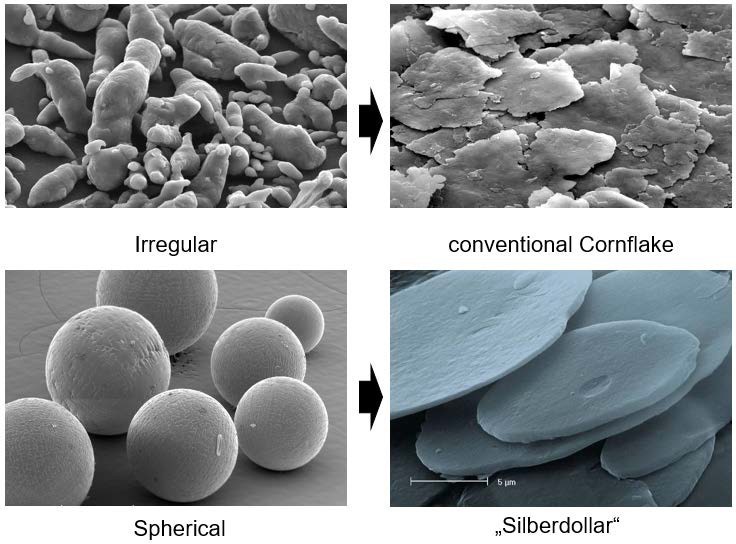
Figure 5: Metallic ink pigments after milling, shapes obtained based on raw materials (irregular or regular aluminum powders), ECKART.
In today’s metallic ink pigment, catalogues the D50-value is usually specified to characterize an metallic ink pigment. A D50-value indicates that 50% of the pigments are smaller than the given value. This corresponds to the use of the D10-value (10% smaller than the value), D90, D99, etc. The value can be an important indicator for how the product can be used. Flexographic inks, for example, usually need finer pigments than the pigments used for gravure printing.
Measuring the particle size distribution of an aluminum metallic ink pigment indicates the amount of fine particles, which are responsible for hiding power, and the amount of coarse particles, which are responsible for brilliance. In automotive coatings, for example, a good aluminum metallic ink pigment has high brilliance and good flop behavior, which is why metallic ink pigments in automotive coatings usually contain fewer fine particles. By comparison, in the printing industry the ideal aluminum pigment has good hiding power and balanced brilliance. This is why aluminum metallic ink pigments for the printing industry usually have a greater amount of fine particles. Another limitation is the cell width of anilox rollers (flexo printing) and gravure cylinders, as well as the mesh opening in screen-printing, which predefines the appropriate particle size distribution for the printing process.
Charting out the full particle size distribution will provide information on the characteristics (D50), the hiding power defined by D10 and the brilliance defined by D90.
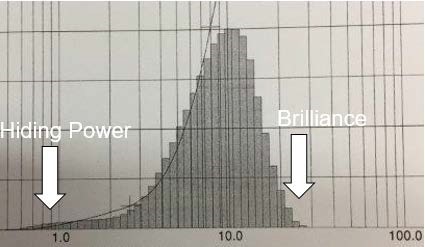
Figure 6: Particle size distribution of a D50=10 µm pigment.
When we compare the pigment microscopy of the cornflake and the silver dollar in Figure 5 and take into account the influence of the particle size distribution, it is already clear that the hiding power of a cornflake grade is usually better than the hiding power of a silver dollar grade. On the other hand, the brilliance of a silver dollar grade is higher than the brilliance of a cornflake grade.
Another observation from the microscopy picture (Figure 5) is that the irregular shape of the cornflake structure creates a longer perimeter than the silver dollar. This is important where a highly shiny effect is required. A larger perimeter in relation to the reflection area (surface area) of a pigment leads to stronger scattering of light (Figure 7). Assuming that the reflection area is already nearly perfect, light will usually be scattered at the edge of a pigment, and the more edge surface (thickness in combination with edge length) available, the lower the distinctiveness of image will be. In some cases this result may be desired, if a silky, smooth metallic effect with a constant reflection over a wide viewing angle is requested. In other cases where high brilliance is requested, a pigment with a high edge area would not be the first choice as it would lead to a high rate of scattering.

Figure 7: Illustration of light scattering at an edge of a metallic pigment.
Types of metallic ink pigments and their appearance
The influence of scattering area on the appearance of a pigment was discussed at the end of Chapter 2.1. The scattering area is defined by the pigment thickness and the perimeter. The more area available, the higher the unfocused scattering of light. Furthermore, fine particles, which can be observed in the particle size distribution, are responsible for good hiding power, and a pigment can be characterized by D50. In conclusion this means that a finer aluminum pigment will generally result in lower distinctiveness of image as long as the thickness of the pigment remains the same. In this case the reflection area will be smaller, and in relation the perimeters and the length of the light scattering edges will be larger.
Some years ago thinner pigments were developed with the aim of reducing the pigment edge area, resulting in very good mirror effects and completing the spectrum of color and distinctiveness for metallic pigments in inks (Figure 8). The pigments that complete the cornflake and silver dollar series are named ‘platinum dollar’ and ‘METALURE®’. These ultra-thin pigments result in very high distinctiveness of image, as can be seen in Figure 8.
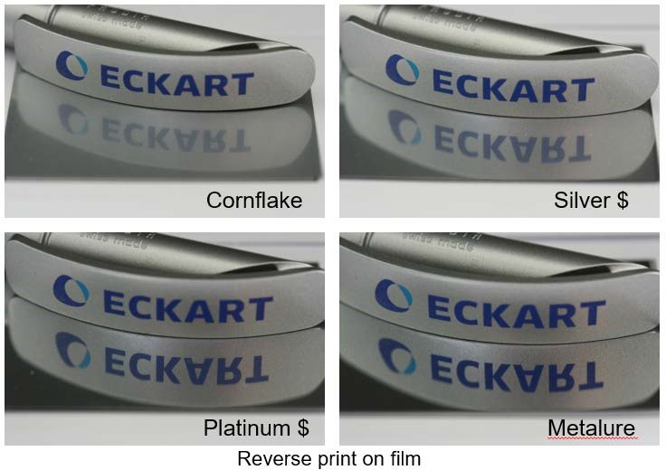
Figure 8: Reverse print of different pigment types on film (cornflake, silver dollar, platinum dollar, METALURE® (Vacuum Metallized Pigment), ECKART.
The images in Figure 8 show the four different types of pigment: cornflake, silver dollar, platinum dollar, and METALURE®, each with a D50 of approximately 10 µm. While the same substrate and printing application are used, the applied inks contain metallic pigments of different particle size distribution, pigment shape and particle thickness. The pigment-to-binder ratio has been adjusted to meet the specific application requirements of each pigment type. The difference in appearance (direct reflection rate/gloss on the reverse printed film) between these four grades is obvious.
The brilliance and mirror effect gradient can be rated as follows (from higher to lower): METALURE® > platinum dollar > silver dollar > cornflake.
In the microscopic image (Figure 9), the increase in surface smoothness with different pigment types can be observed and attributed to their lower particle thickness.
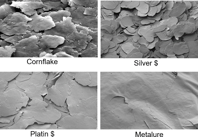
Figure 9: Microscopic images of a 10 µm cornflake, silver dollar, platinum dollar, and METALURE® (Vacuum Metallized Pigments) pigment, ECKART.
Orientation matters
Introduction
The SEM images in Figure 9 show the reflection of the electrons and explain the appearance shown in Figure 8. In addition, the influence of particle thickness can be observed. METALURE® pigments are extremely thin and invariable in particle thickness due to the special manufacturing process using physical vapor deposition (PVD). In a suitable print or coating application, this pigment class is able to achieve the same reflectiveness as metallization. This indicates that thickness and good orientation play a significant role in achieving a good effect in the printed result using metallic ink pigments.
In contrast to yellow or red toner, for example, which are round-shaped, metallic pigments need a distinct orientation parallel to the substrate to achieve good metallic effects, as the target needs to reflect light as well as possible. The spectrum of brilliance from silky smooth effects that can be obtained using cornflakes for optimal mirror effects by METALURE® PVD pigments looks best if there is good orientation with respect to the required distinctiveness, brilliance, mirror and whitish or dark color, depending on the kind of pigment used.
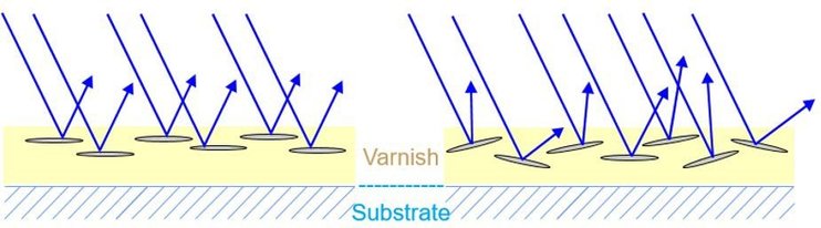
Figure 10: Reflection mechanism of good (left) and fair (right) metallic pigment orientation.
Figure 11: Reflection mechanism using very thin or very thick pigments with the same particle size distribution
Figure 10 shows good and bad light reflection of metallic ink pigments with ideal and poor orientation. This shows that the ink viscosity, application, and drying speed must support the orientation in order to achieve good results. The reflective behavior, which can be assumed from the METALURE® pigments in Figure 9, is drafted in Figure 11. The key to good metallic effect is ideal orientation of the metallic ink pigments.
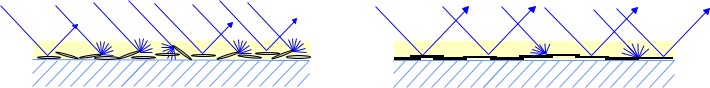
A simple solution to support the balance between technical properties like adhesion, tinting strength, overprintability and appearance can be found already in the milling step. As mentioned in Chapter 2.1, the wet milling process involves a solvent carrier and a lubricant, while the dry milling process only involves a lubricant. The role of the lubricant is to keep the pigments separated while the surface area permanently increases due to the milling process. As the lubricant wets the surface of the aluminum, it also influences the polarity of the pigment surface. If a unipolar lubricant is used the pigment will keep these properties in an ink and stratify after application of the ink onto the surface of the ink film. This behavior is called ‘leafing’ and the metallic flakes are ‘leafing pigments’. In a leafing pigment, the flakes form a dense layer of pigments at the surface of the ink and create an excellent metallic effect. A drawback of leafing pigments is that the overprinting and adhesion properties of the ink layer are decreased
due to the low surface tension and the low embedment of ink resins, resulting in rather poor rub resistance. Another drawback is that due to the dense layer on the surface, toner in the ink will also be overwhelmed by the metallic effect, which results in poor tinting strength in inks containing leafing pigments.
Using more polar lubricants can give the metallic pigment surface greater polarity than the ‘leafing’ pigments. The ‘non-leafing’ effect offers better wetting properties of the pigment. This results in homogenously distributed pigments in the layer of the metallic ink. The technical properties regarding tinting, overprinting, lamination and rub resistance are greatly improved. The metallic effect and reflectivity are slightly lower than with a leafing pigment. Depending on the polarity of the solvents, binders and additives, the polarity differences of leafing and non-leafing pigments are more or less visible. With suitable additives, the effect can be neutralized in some systems. To understand the balance of all properties of the finished ink layer and to avoid wasting time in the lab, it is necessary to understand the influence of polarity on the pigment characteristics so that all technical requirements are met and combined to optimal effect.
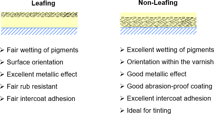
Figure 12: Pigments with leafing (non-polar, left) and non-leafing (polar, right) properties.
Handling and Dispersion of Metallic ink pigments
Understanding the influence of particle size distribution, pigment shape and pigment thickness leads to the question of how to use metallic ink pigments when formulating an ink. The challenge with dispersions is to achieve the separation of each individual particle and embed them perfectly in the binder matrix. If the dispersion is poor and the pigments are not properly separated, agglomerates can be found in the resulting ink, leading to printing defects, poor appearance and poor technical properties. Figure 13 shows images of two cross-sections of substrates coated with metallic ink. The left image shows separated, well dispersed pigments, while the right image shows agglomerated lumps in the binder. One result of such lumps is that a higher load of aluminum pigments is required to obtain sufficient coverage and optical performance of the ink, which leads to more than just increased cost. Another disadvantage of an over filled ink is that there is no binder between the agglomerates, which results in poor network strength of the binder and can result in easy delamination in the binder layer.
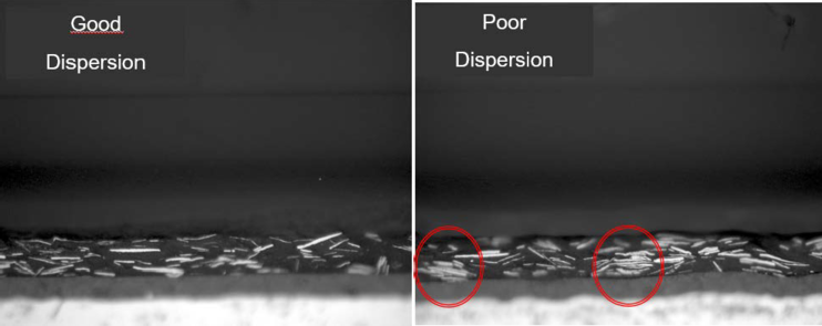
Figure 13: Cross-section of a coated substrate with a metallic binder layer; left image shows good dispersion, right image shows agglomerates (red circles), ECKART.
Other disadvantages can occur during the printing process. Agglomerates can cause printing defects and stripes, once trapped between the doctor blade and cylinder. Furthermore, shear forces along the doctor blade can also break the pigments of the agglomerates, causing color to shift during printing. Depending on the angle of the doctor blade, shear forces caused by a doctor blade at a stiff angle can break pigments in general (even though no agglomerates are images broken) and cause color to shift during printing.
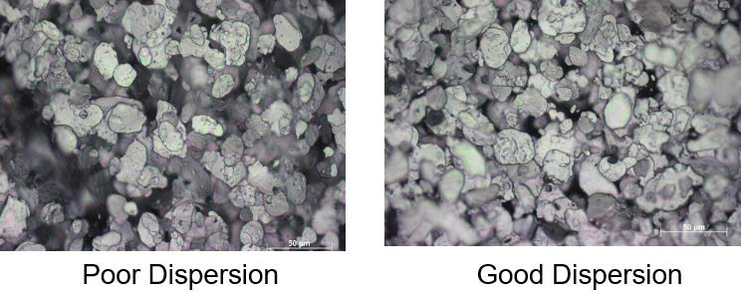
Figure 14: Light-reflected microscopic images of a poor dispersion (right) and a good dispersion (left), ECKART.
Figure 14 shows light-reflected microscopic images of inks with poor and good dispersion of aluminum metallic ink pigments. The image showing poor dispersion has dark areas without pigment coverage, while an optimized dispersion features homogenous distribution of the pigments in the ink. This effect can be used to check dispersion quality in a quick test in the lab, or in production using a draw down or by pouring the dispersion over a glass plate.
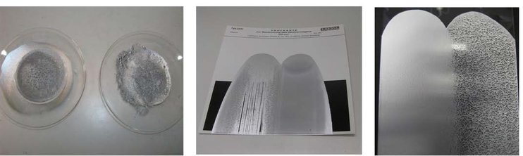
Figure 15: Different quick tests to check dispersion quality in the lab or in production: A) dissolving in organic medium on a watch glass, B) draw down, C) pouring ink over a glass plate, ECKART.
The last figures show the importance of applying sufficient shear forces in the dispersion process for metallic ink pigments in order to ensure that an optimal dispersion can be achieved. On the other hand, excessive shear forces with the wrong agitator, for example, or excessive speed for an aggressive stirrer over too long a time will bend and break the pigments. Aluminum and gold bronze pigments are ductile to a certain extent. Otherwise, milling of powders would not lead to shiny flakes. Excessive shear forces, however, can bend the flake shape or crush the particles into smaller pieces. As mentioned in Chapter 2, increasing the number of very fine particles will lead to a greyish appearance and bending the pigment edges will lead to a larger area for uncontrolled reflection of light. The result will be a very grey appearance with increased hiding power.
Figure 16: Impact of excessive shear forces during stirring on aluminum metallic ink pigments, ECKART.
Figure 16 shows the impact of excessive shear forces on an metallic ink pigment after strong stirring. As shear forces in the production step depend mainly on the size and geometry of the agitator and container used, on the stirring speed and on stirring time, a good balance of all parameters is important for a satisfying result. Another point that has to be taken into account is the upscaling process from lab to production. As the mass of ink used in a production process is much higher than in a lab, the shear forces may be higher than in the dispersion process in the lab. Proper planning of the upscaling process from lab dispersion is essential for the quality of the pigment dispersion at production scale.
Low-shear stirrers commonly used in the ECKART lab are shown in Figure 17. For most aluminum pastes the shear force is high enough to obtain a good dispersion. In some cases a high-shear tooth blade agitator is used (as seen in Figure 18, image 2), but well balanced with stirring speed, time and viscosity.
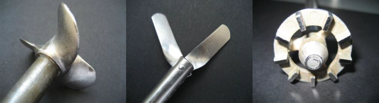
Figure 17: Common agitators used in the lab for ECKART.
For normal dispersions from pastes, pellets, powders and de-dusted powders, the aim is to achieve good wetting of the pigment with the medium before dispersing the pigments. It is therefore a good idea (though not always essential) to soak powders and pelletized pigments and even pastes for a certain time with a dampening medium (solvent).
Pellet: soak in solvent first to support carrier dissolution, start stirring at low speed, increase at the end, balance high speed stirring time to get an optimal dispersion
Dedusted powders: disperse at low speed first, then disperse at moderate speed
Powders: soak in solvent for good wetting of the pigment, start at slow speed and increase at the end, balance high speed stirring time
Paste: start with low to moderate speed, increase at the end
The solvent–pigment mixture is added to a small amount of a binder–solvent mixture (or vice versa), and the mixture is homogenized and then at the end stirred at a higher speed in order to completely dissolve aggregates and lumps. The remaining formulation components of solvent, binder, additives, etc. are then added whilst moderately stirring. The advantage of stirring a larger quantity of pigment in a lower amount of solvent and binder instead of in the ready formulated ink is that the viscosity of the mixture is greater. This approach produces gliding shear forces and disperses pigment particles well without using aggressive agitators, dispersing over a long period of time or using high stirring speeds. Shear forces from fluidal friction (viscosity) are generally very efficient for the dispersion process and bear no risk of flake deformation as compared to the excessive mechanical forces from the agitator and excessive speed and duration.
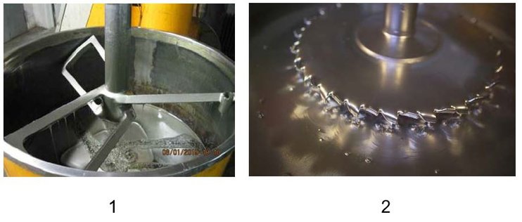
Figure 18: Stirrers used in ECKART's ink production: low shear butterfly mixer (1) and tooth blade (2).
The tooth blade (dissolver disc) is very commonly used in the ink industry to disperse and dissolve toner agglomerates which need high shear forces for dispersion and wetting. By comparison, metallic ink pigments must not be broken or deformed, and aggregated particles must be separated from each other. At ECKART, tooth blade stirrers are usually used to disperse METALURE® PVD pigments. These foil-like pigments are very ductile and have a lower tendency to break. Furthermore, they withstand higher shear due to their low thickness and high ductility.
Example of a production dispersion process
A common procedure for preparing inks pigmented with METALURE® is described below:
Tooth blade diameter: 0.5 x beaker diameter
- Blend 50% binder in solvent with METALURE® pigment at 250 rpm (revolutions per minute)
- After homogenizing, increase speed to 450–500 rpm for 10–30 min
- Check quality of dispersion (Figure 15)
- Add remaining formulation ingredients (solvent, binder, etc.)
- Homogenize mixture at 450 rpm for 10 minutes
Excursus
Dispersion of SYMIC (mica) and LUXAN (glass) flakes
Chapter 3.2 explains why creating a dispersion with flake-like pigments is different compared to inorganic toners like iron oxide, as it is important to keep the flake-like shape during the production and application procedure to assure a metallic effect where cost and appearance are optimized.
Another class of flake-like metallic ink pigment is mica pigments and glass flakes. Mica is a mineral or synthetic mineral built up in silicate layers. Glass flakes are thin and solid. Figure 19 shows microscopic images of the raw materials of the colorful, sparkling ECKART products SYMIC and LUXAN. The images show the identical challenge of dispersion with excessively aggressive agitators and excessive shear forces as in the previous chapter where the dispersion of aluminum pigments was discussed.
In contrast to the bending and breaking aluminum pigments, these mica and glass products are not ductile, so they cannot bend. If excessive shear forces occur, the lamellar structure of mica will break and delaminate, and the glass will break. Low-shear agitators such as butterfly mixers are therefore recommended.
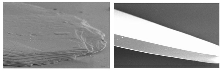
Figure 19: Microscopic images of mica (left) and a glass flake (right), ECKART.
Breaking and delaminating mica and glass flakes will not lead to increased hiding power as with aluminum. The destruction of mica and glass flakes leads to a hazy ink
layer due to small fractions of the mineral glass and mica pigments which scatter light in an uncontrolled manner. The pigment fragments behave like mineral fillers such as sodium carbonate or calcium carbonate. The color of mica and glass pigments is created by a distinctively applied encapsulation layer of titanium dioxide on the surface (Figure 20). By comparison to a dye, the color is created by light transition into layers with different refractive indices. Destruction of the titanium dioxide layer will also lead to a loss of color.
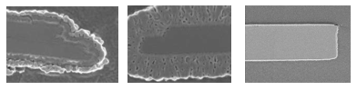
Figure 20: Microscopic cross-sections of titanium dioxide-coated pigments, natural mica (left), synthetic mica (middle), glass flake (right), ECKART.
Shear forces and surface-modified pigments
The discussion above is mainly focused on pigments for solvent-borne inks. The pigments’ chemical composition is quite simple, as they are milled in a solvent along with a lubricant. Nowadays volatile organic compounds (VOCs) are subject to restrictions by governmental regulations with the aim of reducing emissions and protecting the environment. As a result, other chemistries and drying technologies like energy-curing technologies (UV, LED, electron beam and low-energy UV-curing) and waterborne applications are on the rise, forcing companies to look for raw materials and equipment in order to offer optimal solutions for these technologies. For water based inks it is essential to understand that aluminum-based metallic ink pigments may react with water to create hydrogen.
In energy-curing formulations, metal elements like aluminum (or copper and zinc for bronze pigments) can accelerate a gelling or polymerization of monomers and oligomers, if the pigments are not stabilized by chemical surface treatment, resulting in a shorter shelf life. The solution is to apply a protective layer on the aluminum surface in order to establish an inhibiting barrier between the aluminum and the reactive components of the ink. Therefore, two main solutions are common in the market: additive modification and silica encapsulation.
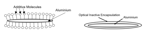
Figure 21: Surface modification technologies for creating a barrier between the ink medium and aluminum: additive modification (left) and silica encapsulation (right).
To seal the aluminum surface with additives, chemical compounds with a high tendency to attack and cohere to the aluminum surface are used. These additives can be single short molecules or larger partially cross-linked compounds. The additives can bond to the aluminum surface and repel water to attack the aluminum surface or block metal ions in the aluminum from starting a chain reaction in energy-curing inks. Silica encapsulation is very effective for achieving ideal sealing of the surface. In this case, silanes are used in a sol-gel reaction to create real cross-linked silica encapsulation. This very efficient barrier creation process also protects the aluminum from reactions with corrosive ink components like binders or additives.
Additive modification is invisible under a microscope, while the silica encapsulation layer can be identified very well. Figure 22 shows a cross-section polish of a silica coated aluminum pigment. The perfect encapsulation indicates that a reaction be tween the ink medium and the pigment is blocked.
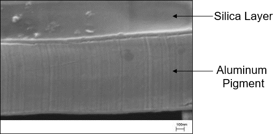
Figure 22: Cross-section polish of an aluminum pigment, showing the protective silica layer, ECKART.
While the possibility of gelling/polymerization is well known in companies that are familiar with energy-curing inks, the effect of a non-stabilized pigment in waterborne ink systems can be quite dangerous. The reaction with water not only produces highly flammable hydrogen gas, but can also create high pressure in ink drums, potentially causing bursting and explosions in the warehouse.
Figure 23: Ink drum in a warehouse under high pressure caused by high pressure due to hydrogen creation.
The dangerous hydrogen gassing of waterborne inks containing aluminum pigments can be prevented by using special additive-stabilized pigments or silica-encapsulated pigments. Another important factor to keep energy-curing and waterborne inks stable is a careful dispersion of the aluminum pigment. High shear forces from mechanical agitators must not be used in order to prevent the aluminum pigment from bending and breaking and avoid the development of new non-stabilized surface areas. Using this production equipment will not only result in a loss of optical characteristics as mentioned in Chapter 3.2, but also a destruction of the protective surface modification, if the pigment is broken as shown in Figure 16.
To ensure that an ink is safe to handle, ECKART measures the amount of hydrogen in an ink. The procedure very closely aligns with real-world conditions, is very reproducible and was implemented as a quality control measure decades ago.
The setup is shown in Figure 24: a glass device is plugged onto a gas-washing bottle. The glass device has a lower and upper chamber, which are linked to each other with a riser pipe. An open plug is attached at the top of the upper chamber. The equipment is set up to allow gas pressure created by hydrogen in the bottle containing the ink to be released. The created pressure pumps a liquid from the lower chamber to the upper chamber and the water is measured as an equivalent to the hydrogen created.
Gassing test procedure:
300 ml of a waterborne ink containing an aluminum pigment is poured into the gas washing bottle and tempered in a water bath for 2 h at 40°C. During tempering, the red screw cap (Figure 24, right image) is kept open to allow pressure produced during the tempering process to be released without pumping water into the upper chamber. Keeping this screw cap closed would falsify the result due pressure changes in the tempering process. After tempering, the cap is closed and the material is stored for 30 days at a constant 40°C. During this time the height of the water level in the upper chamber is measured in milliliters. (A video about the test procedure is available on the ECKART homepage (www.eckart.net)
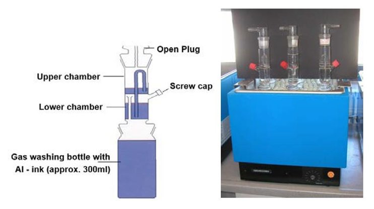
Figure 24: Gassing test to evaluate the stability of water-based pigments and inks, ECKART.
A paste or ink batch passes quality control if the volume of hydrogen produced does not exceed a defined limit during the test period of 30 days. The test is carried out at a standard and constant temperature of 40°C (water bath) to avoid pressure changes caused by temperature changes.
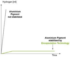
The measured values can be charted out on a graph showing the production of hydrogen over a period of days. Figure 25 shows a comparison of a non-stabilized aluminum pigment versus a silica-encapsulated pigment. It is clear that hydrogen production in a non-stabilized pigment goes up dramatically after a short period of time, while it only goes up slightly with a silica-encapsulated pigment and stops at a very low level after a time.
Figure 25: Results of the gassing test, comparing hydrogen production in a non-stabilized aluminum pigment versus a silica-encapsulated pigment.
Shear forces on the printing machine
The previous chapters provided an overview about what to take into account when balancing shear forces while producing inks containing metallic ink pigments. This discussion gives rise to the question of whether any destructive shear forces can occur during the printing process or printing process preparation.
The printing process starts by stirring the metallic ink before it is used. This process is usually done with a low-shear stirrer at a low rpm. Filling the ink tank and stirring during print trials seldom leads to problems caused by shear forces on flexographic and gravure machines. Usually, the pumping process can create shear forces that can damage flake-type pigments like metallic pigments. Peristaltic pumps are considered the most suitable for the continuous pumping of metallic inks.
Other pump technologies are possible, but the pipe length and pumping distance should be considered. Moving material through a long pipe and possibly pumping material from one floor to a higher floor will increase the pressure in the pipe and with it the shear in the pump system.
Therefore, short pipes are recommended. The component with the highest shear factor in the printing process is usually the doctor blade, particularly at high printing speeds. Metallic ink pigment inks can be printed at a high speed of 200 m/min and higher (gravure).
However, the pigments can be damaged during the printing process. Several factors can cause the flake shape to change: the angle of the doctor blade, excessive pressure from the doctor blade and insufficient lubrication of the cylinder/blade by the ink film. As a result, the color may shift during the print trial from metallic to grey. Adjusting the printing parameters and doctor blade angle can solve this issue.
Choosing the correct substrate
Assuming that the ink is well prepared has a formulation that supports the metallic pigment orientation and has optimized technical properties that maintain the performance of the surface modification; the next step is to choose the optimal substrate. Since the aim is to create a good orientation as shown in Figure 11, having a close look at the substrate surface is important.
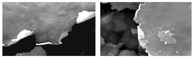
Figure 26 shows microscopic images of different paper qualities. As can be seen on the left side, the base paper is very rough. An applied ink would follow the surface structure and so would the metallic layer. The result would be a metallic ink layer that would reflect light at all angles provided by the surface structure of the base paper.
The appearance would be metallic grey without a focused reflection angle. The human eye would interpret this appearance as less metallic than an ink layer that is applied on a coated paper such as that shown in Figure 26 on the right side. Having a smooth paper structure helps create a very metallic effect.
In this case the light would be reflected at one angle instead of being scattered as with a rough base paper. The same effect can be achieved to a certain extent by using a primer on the paper to create a smooth surface before printing the metallic ink layer. This would significantly improve the metallic effect as well, assuming that the primer layer is able to compensate for the roughness of the paper.
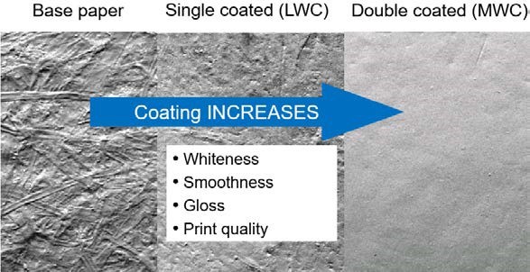
Figure 26: Microscopic images of the surface of base paper and coated papers, SAPPI.
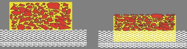
Another possible disadvantage of printing metallic inks on rough base papers is that the base paper can have an absorbing effect. This means that between the process of applying the ink and curing it in the oven or under a UV lamp the ink penetrates into the fibers of the paper. As the metallic pigments are too coarse for the pores of the paper fibers, the paper acts as a filter and the concentration of pigments on the paper surface increases. This leads to a partial separation of binder and pigments. As a result the binder–pigment ratio changes, leading to poor adhesion, poor rub resistance, no over-printability, color loss of tinted metallic inks, etc. The schematic mechanism is shown in Figure 27.
Figure 27: Schematic mechanism of a metallic pigment ink printed on absorbent paper, freshly applied (left) and after ink has absorbed into the paper (right).
As Figure 27 illustrates, the ink is absorbed into the paper and the non-liquid ingredients are concentrated on the substrate surface and cannot be kept in the binder network after drying, because the binder amount on the surface is too low to keep all pigments in the ink layer. This results in defects.
The following experiment was conducted to demonstrate how substrates affect the metallic ink layer:
- A solvent-borne silver metallic effect ink (ink A) and a silver metallic ink with yellow toner (ink B) for gravure prints on paper were formulated
- 4 paper qualities were prepared for the prints
- Wet glue label paper
- Coated label paper for self-adhesive labels
- Carton
- Clay-coated paper for flexible packaging
- The same printing machine was used for all prints
- The cylinders were laser-engraved with 70 l/cm (cylinder 1) and 100 l/cm (cylinder 2)
- Ink A was applied to all papers using cylinder 1
- Ink A was applied to all papers using cylinder 2
- Ink B was applied to all papers using cylinder 1
- Ink B was applied to all papers using cylinder 2
- Prints were done with full paper coverage
- No primer was used
- All machine parameters (e.g. printing speed, printed meters, etc.) were kept constant
After the trial the results were evaluated:
- Hardly any difference between cylinder 1 and cylinder 2
- Gloss measurements (using BYK MicroGloss®) show significant differences in gloss
- Gloss value for wet glue label paper > coated label paper > carton > clay-coated paper
- Significant differences in yellow color intensity with ink B (yellow-tinted)
Images of the resulting prints are shown in Figure 28. As there was hardly any difference between cylinder 1 and cylinder 2 only images of prints with cylinder 1 (70 l/cm) are shown. Besides the resulting difference in gloss there were also differences in the darkness of the silver color. Regarding the yellow-tinted ink (ink B), the yellow, golden color strength is high on wet glue label paper and carton while the color strength on coated label paper and clay-coated paper is rather low. This effect is explained in Figure 27: the yellow-tinted base ink is absorbed by the paper while the paper acts as a filter. With the penetration of the ink into the paper, the yellow toner is also absorbed while the aluminum pigments remain on the paper surface with a reduced binder concentration and yellow toner. As a result, the yellow color strength on coated label paper and clay-coated paper is significantly reduced.
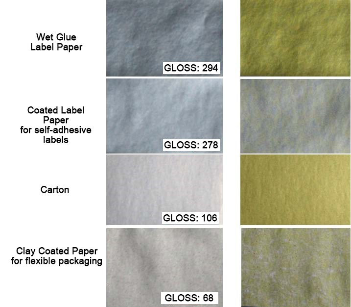
Figure 28: Images of print trial on four different papers, silver ink A (left), yellow-tinted ink B (right), cylinder 1 only.
The print trial with clay-coated label paper shows some significant dots of yellow and silver with yellow ink B. This can be explained by the clay coating. The clays are not homogenously spread over the whole paper and do not seal the surface. As a result, there are some parts of the paper with absorbing properties and some parts without. In this case, the volume of transferred ink is important, which could be observed using cylinder 1 and cylinder 2. As the transferred volume is higher when using a screen ruling of 70 l/cm, the absorbing effect of the paper is visible, but not as significant as when a lower ink volume is applied. Using a cylinder with a screen ruling of 100 l/cm, the inhomogeneous appearance is significant as shown in Figure 29. This can be explained by the absorbance speed of the paper. The paper absorbs the first volume of ink quickly. Then, the absorption speed decreases and absorption competes with drying. It can be concluded that using a higher volume (lines < 70 l/cm) will decrease the inhomogeneous effect or the ink can be adjusted to a higher viscosity in order to decrease the absorption speed. This kind of defect is sometimes observed if the ink is applied on the wrong (uncoated) side of the paper.
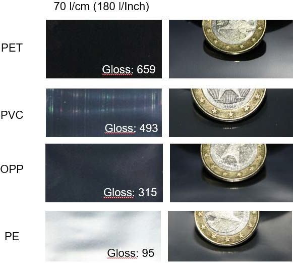
Figure 29: Print trial of silver ink on different film materials using cylinder 1 and ink A.
Different film materials were also evaluated as substrates. Films are available in different chemical compositions and different qualities depending on the production process. The polymeric compounds of a film substrate have the ability to form microcrystalline structures which can influence the printing result. The film production processes,
e.g. stretching, also influence the surface structure and the resulting printing result.
The following setup was chosen for the tests:
- A solvent-borne mirror silver metallic effect ink (ink A) for gravure prints on foil was formulated
- Four foil qualities were prepared for the prints
- PET (polyethylene terephthalate)
- OPP (oriented polypropylene)
- PVC (polyvinylchloride)
- PE (polyethylene)
- The same printing machine was used for all prints
- The cylinder was laser-engraved with a screen ruling of 70 l/cm (cylinder 1)
- Ink A was applied to all film materials using cylinder 1
- Application: reverse printing
- Gloss measurement was performed on the reverse side (the measurement includes the gloss reflection by the substrate)
- For optical comparison, pictures were taken showing the DOI of a coin
- Pictures were taken out of the reflection angle (the darker the picture is, the more focused the reflection and the better the mirror effect)
- No primer was used
- All machine parameters (e.g. printing speed, printed meters, etc.) were kept constant
Results/evaluation:
- Gloss measurements (using BYK MicroGloss®) show significant differences in gloss
- Gloss value for PET > PVC > OPP > PE
- Visual DOI comparison was rated as PET > OPP > PVC > PE
Orientation at ink drying and curing
Now that we have more insight into the dispersion process, high shear avoidance and the selection of the best substrate for a project, about the focus now moves on to the shifts in dried/cured metallic ink appearance depending on the binder chemistry and curing mechanism. When solvent-borne, energy-curing and waterborne ink systems are compared, solvent-borne inks are observed to achieve the best appearance, followed by energy-curing systems, whereas achieving an excellent metallic effect is the hardest challenge for waterborne inks. To understand this order of metallic effects in connection with the binder chemistry, it is necessary to have a look at the curing and drying mechanisms of these chemistries first, keeping everything already discussed about orientation in mind.
Solvent-borne Inks
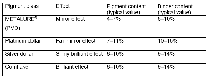
Solvent-borne metallic inks are formulations containing a rather high amount of solvent, additives and one or more binders like PVB, PU, EC, NC or acrylates. The inks are prepared based on the recommendations mentioned in Chapter 3.2 and the binder-to-pigment ratio is adjusted to the required appearance and technical requirements. Typical values can be taken from Table 1.
Figure 30: Typical values of inks containing METALURE®, platinum dollar, silver dollar and cornflake.
The printing viscosity is usually adjusted to 13–15 s DIN 4 cup (19–21 s Zahn 2 cup) for gravure inks and 23–30 s DIN 4 cup (35–40 s Zahn 2 cup). The maximum printing speed depends on the press type, press conditions, substrate and chosen cell volume. For gravure inks, the effect usually improves at a higher speed, as the cylinder cells drain easily and the orientation of the pigment on the substrate is supported by the higher centrifugal forces on the ink droplets in the cylinder cells as the cylinder is spun at a higher rotation speed.
For gravure printing with platinum dollar, PVD , silver dollar and cornflake pigments, the following typical (gravure) cylinder configuration can be used for reference:
Reverse print on transparent film:
- Line count: 70 lines/cm (180 lines/inch)
- Cell diameter: 165 μm
- Graver angle: 120°–130°
For the highest coverage requirements, cylinders with 60 lines/cm (150 lines/inch) and suitable cell depth are recommended. For finer pigment types with high opacity, cylinders with 80–100 lines/cm (200–250 lines/inch) can be used.
Surface print on film:
- Line count: 100 lines/cm (250 lines/inch)
- Cell diameter: 117 μm
- Graver angle:120°–130°
For maximum hiding power, cylinders with 60–80 lines and appropriate cell depth are recommended. The metallic effect may be reduced by printing on excessively heavy films, due to a negative effect on the flake orientation.
For flexo printing with platinum dollar, silver dollar and cornflake pigments, the following typical (anilox roller) configuration can be used for reference:
Both etched and engraved anilox cylinders are suitable (depending on the design). The following parameters have shown to be useful:
Highest brilliance, also for fine details:
- Line count: 100–200 lines/cm
- Cell volume: 8–12 cm3/m2
For higher film weights or hiding power, cylinders with higher cell volumes are recommended. However, the metallic effect may be reduced by printing no excessively heavy films (pigment overlapping and stocking).
Print viscosity: 23–30 s DIN 4 cup (35–45 s Zahn 2 cup)
For flexo printing with PVD pigments (METALURE®), the following typical (anilox roller) configuration can be used for reference:
Reverse print on transparent film:
- Line count: 100–140 lines/cm (250–350 l/inch)
- Cell volume: 10–12 cm³/m² (6.5–7.5 bcm/in²)
Surface print on film:
- Line count: 140–225 lines/cm (350–550 l/inch)
- Cell volume: 7.5–10 cm³/m² (4.5–6.5 bcm/in²)
Depending on the substrate and design, it may be beneficial to use alternative cell counts and volumes. However, the metallic effect may be reduced by printing on excessively heavy films.
Printing speed:
The maximum printing speed depends on the individual press conditions, substrate and chosen cell volume. A printing speed of 150 m/min (500 ft/min) and higher is possible as long as the drying capacity is sufficient.
Printing viscosity: 25–30 s (DIN 4 cup) 35–40 s (Zahn 2 cup)
The ideal printing viscosity also depends on the cylinder configuration.
Applying an optimal solvent-borne ink onto a substrate with a smooth surface will result in a film layer with more than 70% fast evaporating solvents. Even before the substrate gets into oven the solvents will start to evaporate and as a result the film will slowly start to shrink. During this shrinking process, pigments that are not optimally oriented will readjust as the viscosity allows some movement of the pigments. In the end a thin layer of dried ink will stay on the film. This layer contains the lowest amount of binder to keep all pigments in the network and balances the technical properties well. By using a low amount of binder, the aluminum pigment layer is very dense, resulting in high brilliance, optimal hiding power and an optimal color character.
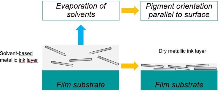
Figure 31: Schematic drying mechanism of solvent-borne inks.
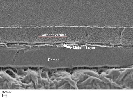
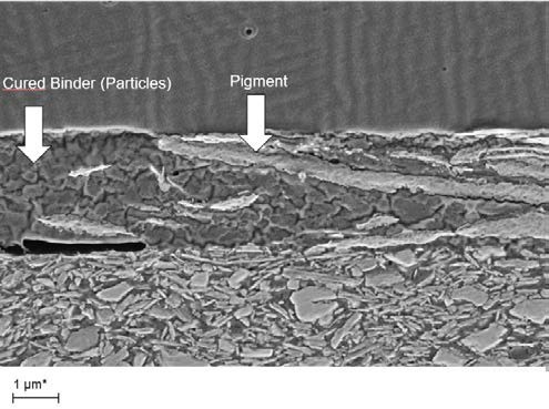
Figure 32 provides an idea of the thickness of an optimal dried solvent-borne metallic ink layer embedded between overprint varnish and primer. The metallic pigment concentration in this thin layer is high to get the best effect. By comparison, the primer has to be applied more thickly in order to compensate for the unevenness of the paper. To prevent the metallic ink layer from resolving and to draw pigments from the metallic layer into the overprint varnish, the metallic layer is usually overprinted with a different chemistry. Otherwise the pigments are highly likely to become disoriented.
Figure 32: Microscopic image of a cross-section of printed paper with a full layer built up: primer, solvent- borne metallic ink, overprint varnish, ECKART.
Energy-curing inks
Energy-curing inks such as e-Beam, UV, low-energy UV and LED inks are more complex to formulate and produce. They are called 100% systems, meaning that the full ink layer is cured with a very low VOC, which usually comes from additives. In general there are no evaporating solvents (sometimes isopropanol is added, for example, to reduce foaming tendency or lower the viscosity). The combination of oligomers and monomers needs to be carefully adjusted to achieve the right curing properties, film flexibility and ink viscosity.
The energy-curing lamp should not be placed too close to the ink chamber. Metallic inks are formulated to a higher reactivity than conventional pigmented UV inks or even non-pigmented varnishes. The reason is that metallic pigments behave like small mirrors to reflect light, including the activating UV light. To get a better appearance with metallic pigments the surface is modified to achieve slight stratification to the surface. As a result, hardly any UV light penetrated through the film to cure the film layer below the metallic pigment layer. To obtain a well cured film, the reactivity of energy-curing systems with incorporated metallic pigments needs to be higher than for a system which contains toner-based CMYK inks. Toners absorb the activating UV light, while metallic pigments reflect the light, so toner-based inks need a lower ink component reactivity for an optimized curing process.
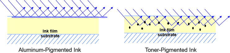
Figure 33: Comparison of the reflective behavior of a metallic pigment and a toner-incorporated ink system.
If lower energy is used to cure the film (e.g. LED or HUV), the ink system needs a photoinitiator, which initiates the curing chain reaction with the emitted wavelength and higher reactivity, as the energy used for curing is lower.
To give the pigments more time for a better orientation, a lower speed and longer distance between the ink chamber and the curing station can improve the metallic appearance. Mixing residual chamber material with fresh material is not recommended, as the shear forces during printing may damage the stabilization of the flakes and misdirect energetic light. This starts the chain reaction on the roller and makes the residual ink material potentially more critical to pre-polymerization/gelling.
The fact that the wet film does not really shrink and the film is ~100% curing affects the orientation significantly. In this case the orientation of the pigments is not supported by a shrinking mechanism and the fact that the binder systems are cured 100% causes the pigments to freeze in whatever orientation they are in, which may result in an inferior appearance if the pigment, ink system and printing parameters are not well adjusted. Figure 34 shows a cross-section of a UV-cured ink film. When compared with the cross-section of a solvent-borne ink film in Figure 32, the film in Figure 34 is thicker and pigments are not very dense and are more disoriented compared to a dry solvent-borne ink film.
Figure 34: Cross-section of a UV-cured ink film, ECKART.
To obtain good technical properties like adhesion after curing a UV ink, the substrate character has to be taken into account. When applying a UV ink or varnish on an absorbing substrate, the UV binder will penetrate into the paper and change the pigment– binder ratio, which can lead to an over-pigmented ink on the substrate surface with poor rub resistance. In such cases the use of a primer is recommended.
Water-based inks
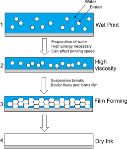
When it comes to water-based inks, the literature tells us that the drying mechanism runs in three steps:
- Waterborne inks contain a stable suspension of binder particles in water. After applying a waterborne ink, high energy is necessary to evaporate water from the system. While the water is evaporating, the binder particles move closer to each other, getting ready for the collapse of the stable suspension. At this stage, the viscosity of the ink layer increases.
- In the next steps the suspension breaks and the binder particles are encouraged to move close to each other.
- In the last step the binder particles flow into each other as the binder bubbles burst, forming a perfect film.
Figure 35: Model of waterborne ink film formation.
The drying mechanism requires a higher thermal energy than solvent-borne ink systems, due to the significantly higher boiling point and lower evaporation rate of water. This requires higher drying temperatures and possibly a slower printing speed in order to obtain a well-dried film. When considering the optical differences between a solvent-based and waterborne ink in terms of appearance, it is important to remember that waterborne systems are inhomogeneous with an organic suspended binder in water. During drying the character of the ink changes from polar to more unipolar and the film does not shrink as significantly and does not support orientation as much as with solvent-borne systems. Additionally, the change in viscosity does not favor the orientation of metallic pigments if they are incorporated in the ink. Figure 36 shows a cross- section of a metallic pigment ink film. The ink layer is thicker than solvent-borne ink layers and the orientation of the pigment is hindered by the binder particles and the viscosity changes during drying. Furthermore, it is interesting to see that the binder dispersion particles do not always flow into each other to create an optimal film, but instead dry and keep the shape of the binder particles. This creates additional light-scattering points and results in a dull appearance when light reflects at the boundary surface of a binder particle.
Figure 36: Cross-section of a dried waterborne metallic pigment film.
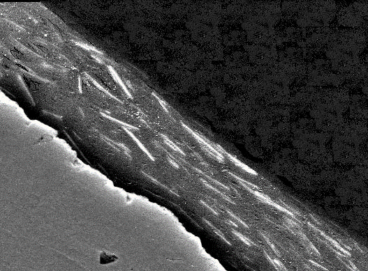
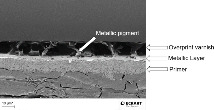
Another parameter that can influence the appearance of waterborne inks (besides the discussed substrate influences) is the enormous energy required to evaporate water. If the printing machine runs too fast or the oven temperature is too low, the waterborne ink film will not dry properly. If an overprint varnish is applied on a poorly dried water- borne ink, the shear of the overprint varnish roller may tear pigments from the metallic ink layer into the overprint varnish layer as can be seen in Figure 37. In this figure a PVD pigment containing waterborne ink was insufficiently dried and an overprint
varnish applied. In this application scenario the PVD pigments are drawn into the over- print varnish and become disoriented, reflecting light in any direction which results in a strongly reduced metallic appearance.
Figure 37: Cross-section of a waterborne ink layer with PVD pigments, including primer and overprint varnish. Due to poor drying of the metallic ink, the pigments are drawn into the overprint varnish layer without any orientation.
For further product information, please visit our website.
For further information about sustainability, please request our ‘ECKART Sustainability Statement’
For further information about the printing process, please request the ‘ECKART Trouble Shooting Guide’
This information and our technical advice- whether verbal, in writing or by way of trials - are given in good faith but without warranty, and this also applies where proprietary right s of third parties are involved. Our advice does not release you from the obligation to verify the information currently provided - especially that contained in our safe ty data and technical information sheets - and to test our products as to their suitability for the intended processes and uses. The application, use and processing of our products and the products manufactured by you on the basis of our technical advice are beyond our control and, therefore, entirely your own responsibility.